Clockwise moment = Anticlockwise moment
100 x X = 2 x 2 = x = 0.04 m
johnmulu answered the question on April 18, 2017 at 13:33
- Figure 3 shows two identical hollow spheres. Sphere A is completely filled with the liquid while B is partially filled with identical liquid.(Solved)
Figure 3 shows two identical hollow spheres. Sphere A is completely filled with the liquid while B is partially filled with identical liquid.
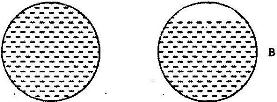
When the two spheres are rolled gently on a horizontal surface, it is observed that the sphere B stops earlier that the sphere A. Explain this observation.
Date posted: April 18, 2017. Answers (1)
- Figure 2 shows a beaker placed on a bench. A block of ice is placed in the beaker as shown(Solved)
Figure 2 shows a beaker placed on a bench. A block of ice is placed in the beaker as shown
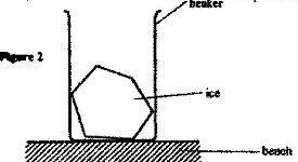
State and explain the change in the stability of the beaker when the ice melts
Date posted: April 18, 2017. Answers (1)
- John carried a uniform post of mass 20 kg horizontally on his shoulders as shown in(Solved)
John carried a uniform post of mass 20 kg horizontally on his shoulders as shown in Fig 6. He placed the post on his shoulder such that the centre of gravity of the pole is 1.0 m behind him. He balanced the post by applying a downwards force F at a point 0.5 m on the part of the pole in front of him.
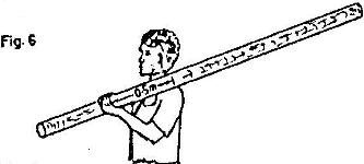
Determine the value of the force F.
Date posted: April 18, 2017. Answers (1)
- In the set up in the Fig. 3, the metre rule is in equilibrium(Solved)
In the set up in the Fig. 3, the metre rule is in equilibrium
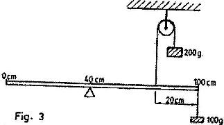
Given that the metre rule is uniform, determine its weight.
Date posted: April 18, 2017. Answers (1)
- Figure 4 shows a uniform metal rod balanced at its centre by different forces.(Solved)
Figure 4 shows a uniform metal rod balanced at its centre by different forces.
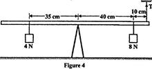
Determine the value of T.
Date posted: April 18, 2017. Answers (1)
- Figure 5 shows a uniform rod 4 m and of mass 2 kg. It is pivoted 1 m from one end and balanced horizontally by a string attached near the other end(Solved)
Figure 5 shows a uniform rod 4 m and of mass 2 kg. It is pivoted 1 m from one end and balanced horizontally by a string attached near the other end

Determine the position where a mass of 5 kg should be placed on the rod so that the rod remains horizontally by a string attached near the other end.
Date posted: April 18, 2017. Answers (1)
- Figure 9 shows a uniform bar in equilibrium under the action of two forces.(Solved)
Figure 9 shows a uniform bar in equilibrium under the action of two forces.
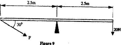
Determine the value of F.
Date posted: April 18, 2017. Answers (1)
- Figure 4 shows a uniform metre rule of weight I N with two weights of 0.18 N and 0.12 N suspended from its ends.(Solved)
Figure 4 shows a uniform metre rule of weight I N with two weights of 0.18 N and 0.12 N suspended from its ends.

Determine how far from the 0.18 N weight a pivot should be placed in order to balance the meter rule
Date posted: April 18, 2017. Answers (1)
- Figure 9 shows a uniform light bar one meter in length in equilibrium under the action of forces F1, F2, F3 and F4. All the forces are in the same plane. Use the information on the figure to answer questions a) and b)(Solved)
Figure 9 shows a uniform light bar one meter in length in equilibrium under the action of forces F1, F2, F3 and F4. All the forces are in the same plane. Use the information on the figure to answer questions
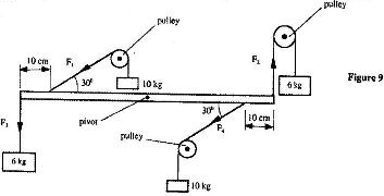
Name one set of forces on the figure that constitutes a couple
Date posted: April 18, 2017. Answers (1)
- Determine the moment of the couple shown in Figure 10.(Solved)
Determine the moment of the couple shown in Figure 10.

Date posted: April 18, 2017. Answers (1)
- Fig. 2 shows a rigid body acted upon by a set of forces. The magnitudes of the forces are as follows: F1 = 3N, F2 = 6N, F3 = 3N, F4 = 4N, F5 = 3N and F6 = 3N.
(Solved)
Fig. 2 shows a rigid body acted upon by a set of forces. The magnitudes of the forces are as follows: F1 = 3N, F2 = 6N, F3 = 3N, F4 = 4N, F5 = 3N and F6 = 3N.
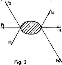
Identify the couple among these forces.
Date posted: April 18, 2017. Answers (1)
- Fig. 5 shows a wheel W pivoted at its centre, O and held stationary by string and a spring. The tension in the string is T and the force on the springs is F. Use this information to answer questions 2 and 3(Solved)
Fig. 5 shows a wheel W pivoted at its centre, O and held stationary by string and a spring. The tension in the string is T and the force on the springs is F. Use this information to answer questions a) and b)
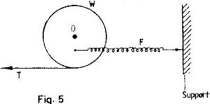
a) State how the magnitude of T and F compare. Give reasons for your answer
b) State what would happen to the wheel if the string snapped
Date posted: April 18, 2017. Answers (1)
- The diagram in Fig. 5 shows a beam of negligible weight balanced by a constant forces P and Q.(Solved)
The diagram in Fig. 5 shows a beam of negligible weight balanced by a constant forces P and Q.
Derive the relations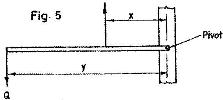 hip between x and y
Date posted: April 18, 2017. Answers (1)
- Figure 1 shows parts of the main scale and vernier scale of a vernier calipers(Solved)
Figure 1 shows parts of the main scale and vernier scale of a vernier calipers
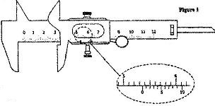
Record the reading indicated.
Date posted: April 18, 2017. Answers (1)
- Figure 1 shows a vernier calipers being used to measure the internal diameter of a tube(Solved)
Figure 1 shows a vernier calipers being used to measure the internal diameter of a tube

Record the diameter of the tube
Date posted: April 18, 2017. Answers (1)
- Figure 1 shows a metal cube of mass 1.75g placed between the jaws of a micrometer screw gauge.(Solved)
Figure 1 shows a metal cube of mass 1.75g placed between the jaws of a micrometer screw gauge.

The magnified portion of the scale is also shown. The reading on the guage when the jaws were fully closed without the cube was 0.012 cm. Use this information and the figure to answer questions a) and b)
a) What is the length of the cube?
b) Determine the density of the metal cube giving your answer correct to three significant figures
Date posted: April 18, 2017. Answers (1)
- Figure 3 shows part of an experimental set up for estimating the diameter of an oil molecule.(Solved)
Figure 3 shows part of an experimental set up for estimating the diameter of an oil molecule.

i) Describe how the oil patch is formed.
ii) Describe one method of determining the diameter of the oil drop
Date posted: April 18, 2017. Answers (1)
- Figure 1 shows a micrometer screw gauge being used to measure the diameter of a ball bearing. A magnified portion of the scale is shown(Solved)
Figure 1 shows a micrometer screw gauge being used to measure the diameter of a ball bearing. A magnified portion of the scale is shown

Date posted: April 18, 2017. Answers (1)
- Figure 1 shows a micrometer screw gauge being used to measure the diameter of a metal rod. The thimble scale has 50 divisions(Solved)
Figure 1 shows a micrometer screw gauge being used to measure the diameter of a metal rod. The thimble scale has 50 divisions

What is the reading shown?
Date posted: April 18, 2017. Answers (1)
- What is the reading on the vernier calipers shown in Figure 1?(Solved)
What is the reading on the vernier calipers shown in Figure 1?

Date posted: April 18, 2017. Answers (1)