Taking moments = Anticlockwise moments
0.6 x 70 cm = Wt x 30 cm;
Wt = mg = 1.4 N
Taking moments = Anticlockwise moments
0.6 x 70 cm = Wt x 30 cm;
Wt = mg = 1.4 N
johnmulu answered the question on April 19, 2017 at 07:12
-
Figure 3 shows a rectangular block of wood with a hollow section (inside) at the position shown. The block is resting on a Horizontal bench
(Solved)
Figure 3 shows a rectangular block of wood with a hollow section (inside) at the position shown. The block is resting on a Horizontal bench
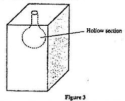
i) State the effect on the stability of the block when the hollow section is filled with water
ii) Explain your answer in (i) above.
Date posted:
April 19, 2017
.
Answers (1)
-
Figure 3 shows two identical trolleys with loads A and B. The loads are identical in shape and size
(Solved)
Figure 3 shows two identical trolleys with loads A and B. The loads are identical in shape and size
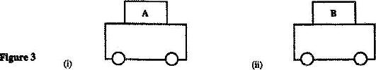
Given that the density of A is greater than that of B, explain why the trolley in Figure 3 (ii) is more stable
Date posted:
April 19, 2017
.
Answers (1)
-
Figure 3 shows two identical hollow spheres. Sphere A is completely filled with the liquid while B is partially filled with identical liquid.
(Solved)
Figure 3 shows two identical hollow spheres. Sphere A is completely filled with the liquid while B is partially filled with identical liquid.
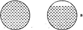
When the two spheres are rolled gently on a horizontal surface, it is observed that the sphere B stops earlier that the sphere A. Explain this observation.
Date posted:
April 18, 2017
.
Answers (1)
-
Figure 2 shows a beaker placed on a bench. A block of ice is placed in the beaker as shown
(Solved)
Figure 2 shows a beaker placed on a bench. A block of ice is placed in the beaker as shown
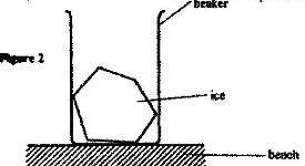
State and explain the change in the stability of the beaker when the ice melts
Date posted:
April 18, 2017
.
Answers (1)
-
Figure 4 shows a uniform metal rod balanced at its centre by different forces.
(Solved)
Figure 4 shows a uniform metal rod balanced at its centre by different forces.
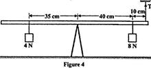
Determine the value of T.
Date posted:
April 18, 2017
.
Answers (1)
-
Figure 5 shows a uniform rod 4 m and of mass 2 kg. It is pivoted 1 m from one end and balanced horizontally by a string attached near the other end
(Solved)
Figure 5 shows a uniform rod 4 m and of mass 2 kg. It is pivoted 1 m from one end and balanced horizontally by a string attached near the other end
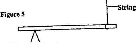
Determine the position where a mass of 5 kg should be placed on the rod so that the rod remains horizontally by a string attached near the other end.
Date posted:
April 18, 2017
.
Answers (1)
-
Figure 9 shows a uniform bar in equilibrium under the action of two forces.
(Solved)
Figure 9 shows a uniform bar in equilibrium under the action of two forces.
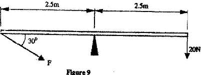
Determine the value of F.
Date posted:
April 18, 2017
.
Answers (1)
-
Figure 4 shows a uniform metre rule of weight I N with two weights of 0.18 N and 0.12 N suspended from its ends.
(Solved)
Figure 4 shows a uniform metre rule of weight I N with two weights of 0.18 N and 0.12 N suspended from its ends.
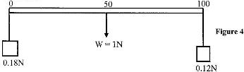
Determine how far from the 0.18 N weight a pivot should be placed in order to balance the meter rule
Date posted:
April 18, 2017
.
Answers (1)
-
Figure 1 shows a vernier calipers being used to measure the internal diameter of a tube
(Solved)
Figure 1 shows a vernier calipers being used to measure the internal diameter of a tube

Record the diameter of the tube
Date posted:
April 18, 2017
.
Answers (1)
-
Figure 3 shows part of an experimental set up for estimating the diameter of an oil molecule.
(Solved)
Figure 3 shows part of an experimental set up for estimating the diameter of an oil molecule.

i) Describe how the oil patch is formed.
ii) Describe one method of determining the diameter of the oil drop
Date posted:
April 18, 2017
.
Answers (1)
-
Figure 1 shows a micrometer screw gauge being used to measure the diameter of a ball bearing. A magnified portion of the scale is shown
(Solved)
Figure 1 shows a micrometer screw gauge being used to measure the diameter of a ball bearing. A magnified portion of the scale is shown

Date posted:
April 18, 2017
.
Answers (1)
-
Figure 1 shows a micrometer screw gauge being used to measure the diameter of a metal rod. The thimble scale has 50 divisions
(Solved)
Figure 1 shows a micrometer screw gauge being used to measure the diameter of a metal rod. The thimble scale has 50 divisions

What is the reading shown?
Date posted:
April 18, 2017
.
Answers (1)
-
The micrometer screw gauge represented by Fig.1 has thimble scale of 50 divisions. What is the reading shown?
(Solved)
The micrometer screw gauge represented by Fig.1 has thimble scale of 50 divisions. What is the reading shown?

Date posted:
April 18, 2017
.
Answers (1)
-
Figure 2 shows a soft iron bar AB placed in a coil near a freely suspended magnet.
(Solved)
Figure 2 shows a soft iron bar AB placed in a coil near a freely suspended magnet.

Explain the observation made when the switch is closed.
Date posted:
April 18, 2017
.
Answers (1)
-
Figure 2 shows a horse – shoe magnet whose poles are labeled and two other magnets near it. Iron nails are attracted to the lower ends of the magnets as shown.
(Solved)
Figure 2 shows a horse – shoe magnet whose poles are labeled and two other magnets near it. Iron nails are attracted to the lower ends of the magnets as shown.

Identify the poles marked X and Y
Date posted:
April 18, 2017
.
Answers (1)
-
Figure 7 shows how magnets are stored in pairs with keepers at the ends
(Solved)
Figure 7 shows how magnets are stored in pairs with keepers at the ends. Explain how this method of storing helps in retaining magnetic longer

Date posted:
April 18, 2017
.
Answers (1)
-
In an experiment to magnetize two substances p and Q using electric currents, two curves (graphs) were obtained as shown in fig. 1
(Solved)
In an experiment to magnetize two substances p and Q using electric currents, two curves (graphs) were obtained as shown in fig. 1

Using this information in Fig. 1 explain the difference between the substances P and Q with reference to the domain theory
Date posted:
April 18, 2017
.
Answers (1)
-
Figure 4 shows the cross-section of a dry cell. Use the information on the figure to answer question a) and b)
(Solved)
Figure 4 shows the cross-section of a dry cell. Use the information on the figure to answer question a) and b)

a) Name the parts labeled A and B
b) State the use of manganese (IV) oxide in the cell.
Date posted:
April 18, 2017
.
Answers (1)
-
Figure 12, shows an electrical circuit including three switches, S1, S2, S3 and three identical lamps L1, L2, L3. A constant potential difference is applied across X and Y.
(Solved)
Figure 12, shows an electrical circuit including three switches, S1, S2, S3 and three identical lamps L1, L2, L3. A constant potential difference is applied across X and Y.

i) Other than L1, state the lamp that will light when S1 and S2 are closed.
ii) How does the brightness in L1 in (i) above compare with its brightness when all the switches are closed?
iii) Explain the observation in (ii) above
Date posted:
April 18, 2017
.
Answers (1)
-
Figure 7 shows the features of a dry cell (Leclanche’s). Use the information in the figure to answer the questions a and b
(Solved)
Figure 7 shows the features of a dry cell (Leclanche’s). Use the information in the figure to answer the questions a and b

a) State the polarities of the parts labeled A and B.
b) Name the chemical substance in the parts labeled C and D
Date posted:
April 18, 2017
.
Answers (1)