When the switch is closed, current flows and the iron core in the solenoid is magnetized attracting the flat spring. This causes a break in the contact with the iron nail thereby disconnecting current. Magnetism is lost releasing the spring and the process is repeated
johnmulu answered the question on April 19, 2017 at 07:54
- Figure 8 shows a current-carrying coil in a magnetic field (Solved)
Figure 8 shows a current-carrying coil in a magnetic field
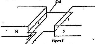
State two ways of increasing the force on the coil
Date posted: April 19, 2017. Answers (1)
- Figure 8 shows two parallel thick copper conductors connected to a d.c. power supply. A rider made from a thin copper wire is placed on the conductors(Solved)
Figure 8 shows two parallel thick copper conductors connected to a d.c. power supply. A rider made from a thin copper wire is placed on the conductors
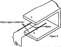
State and explain what is observed on the rider when the switch is closed.
Date posted: April 19, 2017. Answers (1)
- Figure 2 shows the circuit of a simple telephone receiver(Solved)
Figure 2 shows the circuit of a simple telephone receiver. When the telephone is lifted a steady current flows through the solenoids. When a person speaks into the microphone on the other side, a varying current flows. These two currents are shown in Figure 2 (b)
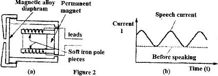
i) State the reason why the solenoids are wound in opposite directions around the soft-iron core pieces as shown.
ii) Explain how the speech current from the microphone is converted into sound in the direction receiver.
iii) State and explain the effect of replacing the soft iron core pieces with steel core pieces
Date posted: April 19, 2017. Answers (1)
- Figure 16 shows a wire XY at right angles to a magnetic field. XY is part of circuit containing a galvanometer.(Solved)
Figure 16 shows a wire XY at right angles to a magnetic field. XY is part of circuit containing a galvanometer.

When XY is moved the current flows in the direction shown. State the direction in which XY is moved.
Date posted: April 19, 2017. Answers (1)
- In the set up in Fig. 5, the suspended metre rule in equilibrium balanced by the magnet and the weight shown. The iron core is fixed to the bench.(Solved)
In the set up in Fig. 5, the suspended metre rule in equilibrium balanced by the magnet and the weight shown. The iron core is fixed to the bench.
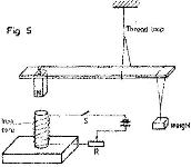
i) State and explain the effect on the metre rule when the switch S, is closed.
ii) What would be the effect of reversing the battery terminals?
iii) Suggest how the set up in figure 5 can be adapted to measure the current flowing in the current circuit.
Date posted: April 19, 2017. Answers (1)
- Figure 12 shows a set up used to determine the mass of a solid S. The rod is pivoted at its centre of gravity C.(Solved)
Figure 12 shows a set up used to determine the mass of a solid S. The rod is pivoted at its centre of gravity C.

i) State two measurements that need to be made to determine the mass of solid S.
ii) Write an expression to show how the measurements in (i) above are used to obtain the mass of S.
Date posted: April 19, 2017. Answers (1)
- Figure 1 shows a lorry moving on an inclined section of a straight road. At the back is a chain hanging from a point on a horizontal axis through the centre of gravity of a lorry.(Solved)
Figure 1 shows a lorry moving on an inclined section of a straight road. At the back is a chain hanging from a point on a horizontal axis through the centre of gravity of a lorry.

State with a reason whether the lorry is stable or not stable.
Date posted: April 19, 2017. Answers (1)
- Figure 6 shows an athlete lifting weights while standing with the feet apart(Solved)
Figure 6 shows an athlete lifting weights while standing with the feet apart

Explain why standing with the feet apart improves the athlete’s stability.
Date posted: April 19, 2017. Answers (2)
- Figure 3 shows a uniform metre rule pivoted at the 30 cm mark. It is balanced by a weight of 2 N suspended at the 5 cm mark.(Solved)
Figure 3 shows a uniform metre rule pivoted at the 30 cm mark. It is balanced by a weight of 2 N suspended at the 5 cm mark.

Determine the weight of the metre rule
Date posted: April 19, 2017. Answers (1)
- Figure 5 shows a uniform bar of length 1.0 m pivoted near one end. The bar is kept in equilibrium by a spring balance as shown.(Solved)
Figure 5 shows a uniform bar of length 1.0 m pivoted near one end. The bar is kept in equilibrium by a spring balance as shown.
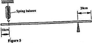
Given that the reading of the spring balance is 0.6 N, determine the weight of the bar
Date posted: April 19, 2017. Answers (1)
- Figure 3 shows a bimetallic strip with a wooden handle, suspended horizontally using a thin thread.(Solved)
Figure 3 shows a bimetallic strip with a wooden handle, suspended horizontally using a thin thread.
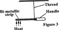
The strip is heated at the point shown. Explain why the system tips to the right
Date posted: April 19, 2017. Answers (1)
- The system in Figure 9 is in equilibrium.(Solved)
The system in Figure 9 is in equilibrium.
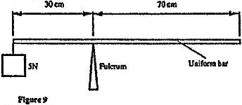
Determine the weight of the bar
Date posted: April 19, 2017. Answers (1)
- Figure 3 shows a rectangular block of wood with a hollow section (inside) at the position shown. The block is resting on a Horizontal bench(Solved)
Figure 3 shows a rectangular block of wood with a hollow section (inside) at the position shown. The block is resting on a Horizontal bench
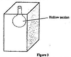
i) State the effect on the stability of the block when the hollow section is filled with water
ii) Explain your answer in (i) above.
Date posted: April 19, 2017. Answers (1)
- Figure 3 shows two identical trolleys with loads A and B. The loads are identical in shape and size(Solved)
Figure 3 shows two identical trolleys with loads A and B. The loads are identical in shape and size

Given that the density of A is greater than that of B, explain why the trolley in Figure 3 (ii) is more stable
Date posted: April 19, 2017. Answers (1)
- Figure 7 shows a non-uniform log of mass 100 kg balanced on the pivot by a 2 kg mass placed as shown.(Solved)
Figure 7 shows a non-uniform log of mass 100 kg balanced on the pivot by a 2 kg mass placed as shown.
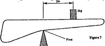
Determine the distance of the centre of gravity of the log from the pivot.
Date posted: April 18, 2017. Answers (1)
- Figure 3 shows two identical hollow spheres. Sphere A is completely filled with the liquid while B is partially filled with identical liquid.(Solved)
Figure 3 shows two identical hollow spheres. Sphere A is completely filled with the liquid while B is partially filled with identical liquid.
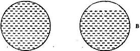
When the two spheres are rolled gently on a horizontal surface, it is observed that the sphere B stops earlier that the sphere A. Explain this observation.
Date posted: April 18, 2017. Answers (1)
- Figure 2 shows a beaker placed on a bench. A block of ice is placed in the beaker as shown(Solved)
Figure 2 shows a beaker placed on a bench. A block of ice is placed in the beaker as shown
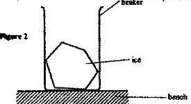
State and explain the change in the stability of the beaker when the ice melts
Date posted: April 18, 2017. Answers (1)
- John carried a uniform post of mass 20 kg horizontally on his shoulders as shown in(Solved)
John carried a uniform post of mass 20 kg horizontally on his shoulders as shown in Fig 6. He placed the post on his shoulder such that the centre of gravity of the pole is 1.0 m behind him. He balanced the post by applying a downwards force F at a point 0.5 m on the part of the pole in front of him.
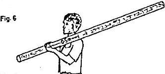
Determine the value of the force F.
Date posted: April 18, 2017. Answers (1)
- In the set up in the Fig. 3, the metre rule is in equilibrium(Solved)
In the set up in the Fig. 3, the metre rule is in equilibrium
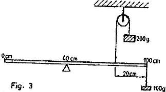
Given that the metre rule is uniform, determine its weight.
Date posted: April 18, 2017. Answers (1)
- Figure 4 shows a uniform metal rod balanced at its centre by different forces.(Solved)
Figure 4 shows a uniform metal rod balanced at its centre by different forces.
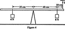
Determine the value of T.
Date posted: April 18, 2017. Answers (1)