(i) 1.5 Vo
(ii) V = IR
1.2 = I x 3 - I = 0.4 A
(iii) E = V + Ir
1.5 = 1.2 + 0.4r
r = 0.30.4 = 0.75 ohms
johnmulu answered the question on May 23, 2017 at 12:36
- Figure 9 shows the graph of the relationship between current I and potential difference V for two tungsten filament lamps X and Y. The normal working voltages for the lamp X and lamp Y are 2.5 V and 3.0 V respectively. (Solved)
Figure 9 shows the graph of the relationship between current I and potential difference V for two tungsten filament lamps X and Y. The normal working voltages for the lamp X and lamp Y are 2.5 V and 3.0 V respectively.

(a) Explain the change in the shape of the curves as the current increases.
(b) Determine the resistance of the lamps X at the normal working voltage.
(c) The lamps are now connected in a series circuit in which a current of 0.4 A flows. Find the potential differences across lamp Y.
Date posted: May 23, 2017. Answers (1)
- Figure 3 shows part of an electrical circuit. The current through the 18 ohms resistor is observed to be 2A.(Solved)
Figure 3 shows part of an electrical circuit. The current through the 18 ohms resistor is observed to be 2A.

State the value of the circuit through each of the 10 ohm resistors.
Date posted: May 23, 2017. Answers (1)
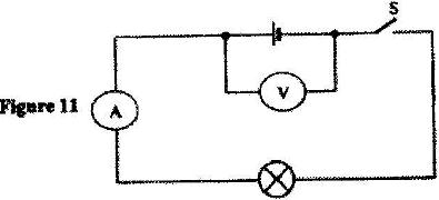
- In figure 11 the voltmeter reads 2.1 V when the switch is open. When the switch is closed, the voltmeter reads 1.8 V and the ammeter reads 0.1 A. (Solved)
In figure 11 the voltmeter reads 2.1 V when the switch is open. When the switch is closed, the voltmeter reads 1.8 V and the ammeter reads 0.1 A.
 ()
()
Determine:
(i) The e.m.f of the cell.
(ii) The internal resistance of the cell.
(iii) The resistance of the lamp.
Date posted: May 23, 2017. Answers (1)
- Figure 6 shows a circuit in which a battery of negligible internal resistance, two resistors a capacitor, a voltmeter and a switch are connected. (Solved)
Figure 6 shows a circuit in which a battery of negligible internal resistance, two resistors a capacitor, a voltmeter and a switch are connected.

Giving a reason for your answer in each case, state the reading of the voltammeter, V, when the switch is (i) Open (ii) Closed
Date posted: May 23, 2017. Answers (1)
- The cell in Figure 10 has an e.m.f of 2.1 V and negligible internal resistance. (Solved)
The cell in Figure 10 has an e.m.f of 2.1 V and negligible internal resistance.

Determine the
(i) Total resistance in the circuit
(ii) Current in the circuit
(iii) Reading of the voltmeter
Date posted: May 23, 2017. Answers (1)
- When the device,X is connected in the circuit below, the voltage across it is 0.70 V.(Solved)
When the device,X is connected in the circuit below, the voltage across it is 0.70 V.

Calculate the value of the resistance R.
Date posted: May 23, 2017. Answers (1)
- The graph in Figure 9 shows the current-voltage characteristics of a certain device, X(Solved)
The graph in Figure 9 shows the current-voltage characteristics of a certain device, X

(i) State with a reason whether the device obeys Ohm's law
(ii) Determine the resistance of the device, X when the current through it is 60 mA
Date posted: May 23, 2017. Answers (1)
- The graph below shows the voltage-current relationship for a certain conductor. (Solved)
The graph below shows the voltage-current relationship for a certain conductor.

Determine the resistance of the conductor.
Date posted: May 23, 2017. Answers (1)
- Figure 4 shows an electrical circuit. When the switch is closed the ammeter reading is 0.3 A. (Solved)
Figure 4 shows an electrical circuit. When the switch is closed the ammeter reading is 0.3 A.

Determine the voltmeter reading.
Date posted: May 23, 2017. Answers (1)
- The ammeter in the circuit in Figure 11 has negligible resistance. When the switch S is closed, the ammeter reads 0.10 A. Determine the internal resistance of the battery. (Solved)
The ammeter in the circuit in Figure 11 has negligible resistance. When the switch S is closed, the ammeter reads 0.10 A. Determine the internal resistance of the battery.

Date posted: May 23, 2017. Answers (1)
- The internal resistance of the cell, E in Fig. 3 is 0.5 ohms. (Solved)
The internal resistance of the cell, E in Fig. 3 is 0.5 ohms.

Determine the ammeter reading when the switch, S is closed.
Date posted: May 23, 2017. Answers (1)
- The diagram in Fig. 2 represent an electric circuit in which five resistors are connected to be a battery of e.m.f. 4.0 V and of negligible internal resistance. (Solved)
The diagram in Fig. 2 represent an electric circuit in which five resistors are connected to be a battery of e.m.f. 4.0 V and of negligible internal resistance.

Determine:
(i) The current flowing through the 5.5 resistor
(ii) The potential difference between Y and Q.
Date posted: May 23, 2017. Answers (1)
- A thermistor, TH, is connected in parallel with a bulb as shown in Fig. 3.(Solved)

The bulb is lit. When the thermistor is steadily heated the brightness of the bulb reduces. Explain observation.
Date posted: May 23, 2017. Answers (1)
- Figure 10 shows a trolley of weight 20 N pulled by a force of 4 N from the bottom to the top of an inclined plane at a uniform speed. (Solved)
Figure 10 shows a trolley of weight 20 N pulled by a force of 4 N from the bottom to the top of an inclined plane at a uniform speed.

(i) State the value of the force acting downwards along the inclined plane.
(ii) Explain how the value in part (a)(i) is obtained.
Date posted: May 16, 2017. Answers (1)
- Figure 10 shows a pulley system used to raise a load by applying an effort of 500 N(Solved)
Figure 10 shows a pulley system used to raise a load by applying an effort of 500 N

State the:
(i) Velocity ratio of the system.
(ii) Purpose of pulley 2.
(iii) Given that the machine has an efficiency of 80%, determine the maximum load that can be raised.
Date posted: May 16, 2017. Answers (1)
- Figure 16 shows a screw jack whose screw has a pitch of 1 mm, and has a handle of 25 cm long.(Solved)
Figure 16 shows a screw jack whose screw has a pitch of 1 mm, and has a handle of 25 cm long.

Determine the velocity ratio of the jack.
Date posted: May 16, 2017. Answers (1)
- Figure 7 shows a mass of 30 kg being pulled from point P to point Q, with a force of 200 N parallel(Solved)
Figure 7 shows a mass of 30 kg being pulled from point P to point Q, with a force of 200 N parallel to an inclined plane. The distance between P and Q is 22.5 m. In being moved from P and Q the mass is raised through a vertical height of 7.5 m.
 Determine the work done:
(I) By the force;
(II) On the mass;
(III) To overcome friction.
Date posted: May 16, 2017. Answers (1)
- Figure 9 shows a drum of mass 90 kg being rolled up a plane inclined at 25o to the horizontal. The force F applied is 420N and the distance moved by the drum along the plane is 5.2 m. (Solved)
Figure 9 shows a drum of mass 90 kg being rolled up a plane inclined at 25o to the horizontal. The force F applied is 420N and the distance moved by the drum along the plane is 5.2 m.

Determine:
(i) The work done by the effort;
(ii) The work done in raising the drum;
(iii) The efficiency of the inclined plane as a machine.
Date posted: May 16, 2017. Answers (1)
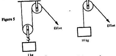
- Figure 5 shows two pulley systems being used to raise different loads. The pulleys are identical. (Solved)
Figure 5 shows two pulley systems being used to raise different loads. The pulleys are identical.

State one reason why system B may have a higher efficiency than system A.
Date posted: May 16, 2017. Answers (1)
- A body of mass 60 kg is pulled at a uniform velocity up smooth inclined surface as shown in Figure 11.(Solved)
A body of mass 60 kg is pulled at a uniform velocity up smooth inclined surface as shown in Figure 11.

If the distance moves along the incline is 4.0 m, determine work done by the force F.
Date posted: May 16, 2017. Answers (1)