(i) The milliammter deflects to maximum then decreases to zero.
(ii) Increases from zero to maximum
johnmulu answered the question on May 27, 2017 at 06:07
- Figure 7 shows capacitors A and B connected in series with a battery of e.m.f 4 V
(Solved)
Figure 7 shows capacitors A and B connected in series with a battery of e.m.f 4 V

Determine:
(i) The effective capacitance of the circuit.
(ii) The quantity of charge in capacitor A.
Date posted: May 27, 2017. Answers (1)
- Figure 3 shows a voltmeter connected across two charged parallel plates. (Solved)
Figure 3 shows a voltmeter connected across two charged parallel plates.

When a thin sheet of mica is inserted between the plates, the voltmeter reading is observed to reduce. Explain this observation.
Date posted: May 27, 2017. Answers (1)
- Figure 8, shows a circuit that may be used to charge a capacitor. (Solved)
Figure 8, shows a circuit that may be used to charge a capacitor.

(i) State the observation on the milliammmeter when the circuit is switched on.
(ii) Explain the observation in (i) above.
Date posted: May 27, 2017. Answers (1)
- Figure 7 shows a pair of parallel plates of a capacitor connected to a battery. The upper plates is displaced slightly to the left. (Solved)
Figure 7 shows a pair of parallel plates of a capacitor connected to a battery. The upper plates is displaced slightly to the left.

State with reason the effect of this movement on the capacitance.
Date posted: May 27, 2017. Answers (1)
- The capacitors in the circuit in Figure 14 are identical and initially uncharged. (Solved)
The capacitors in the circuit in Figure 14 are identical and initially uncharged.

Switch S1 is closed while switch S2 remains open. After sometimes, switch S1 is opened and switch S2 closed. Determine the final reading of the voltmeter, V.
Date posted: May 26, 2017. Answers (1)
- Figure 20 shows three capacitors connected between two points A and B. (Solved)
Figure 20 shows three capacitors connected between two points A and B.

Determine the capacitance across AB.
Date posted: May 26, 2017. Answers (1)
- Figure 11 shows part of the circuit containing two capacitors of 2uF and 3uF respectively
(Solved)
Figure 11 shows part of the circuit containing two capacitors of 2uF and 3uF respectively

Determine the p.d across AB given that the total charge in the capacitors is 1 x 10⁻⁴ coulombs.
Date posted: May 26, 2017. Answers (1)
- Figure 7 shows a "windmill" which when connected to the dome of a positively charged Van de Graff generator is observed to rotate as indicated. A, B, C and D are sharp points. (Solved)
Figure 7 shows a "windmill" which when connected to the dome of a positively charged Van de Graff generator is observed to rotate as indicated. A, B, C and D are sharp points.

Explain how this rotation is caused.
Date posted: May 26, 2017. Answers (1)
- Figure 15 shows a battery of e.m.f. 3.0 V connected in series with two capacitors. (Solved)
Figure 15 shows a battery of e.m.f. 3.0 V connected in series with two capacitors.

Determine the charge stored in the combined capacitors when the switch S is closed.
Date posted: May 26, 2017. Answers (1)
- Figure 7 shows a sharp pin fixed on a cap of leaf electroscope. The electroscope is highly charged and then left for some time. (Solved)
Figure 7 shows a sharp pin fixed on a cap of leaf electroscope. The electroscope is highly charged and then left for some time.
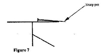
Explain why the leaf collapses.
Date posted: May 26, 2017. Answers (1)
- Fig 5 shows a circuit for changing and discharging a capacitor, c, through a variable resistor R. X, Y and T are points on a two-way switch. (Solved)
Fig 5 shows a circuit for changing and discharging a capacitor, c, through a variable resistor R. X, Y and T are points on a two-way switch.

Explain how the charging and discharging processes are achieved.
Date posted: May 26, 2017. Answers (1)
- Figure 8 represents two parallel plates of a capacitor separated by a distance d. Each plate has an area of A square units. (Solved)
Figure 8 represents two parallel plates of a capacitor separated by a distance d. Each plate has an area of A square units.

Suggest two adjustments that can be made so as to reduce the effective capacitance.
Date posted: May 26, 2017. Answers (1)
- Figure 9 shows two speakers S1 and S2 which produce sound of the same frequency. They are placed equidistant from a line AB and a line PQ. (PQ is perpendicular to line AB).(Solved)
Figure 9 shows two speakers S1 and S2 which produce sound of the same frequency. They are placed equidistant from a line AB and a line PQ. (PQ is perpendicular to line AB).
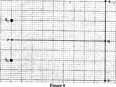
(i) A student walking from A and B hears alternating loud and soft sounds. Explain why at some point the sound heard is soft.
(ii) The student now walks along line PQ. State with reason the nature of the sound the student hears.
Date posted: May 26, 2017. Answers (1)
- Figure 13 shows two identical dippers A and B vibrating in water in phase with each other. The dippers have the same constant frequency and amplitude. The waves produced are observed along line MN:(Solved)
Figure 13 shows two identical dippers A and B vibrating in water in phase with each other. The dippers have the same constant frequency and amplitude. The waves produced are observed along line MN:
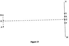
It is observed that the amplitude are maximum at points P and R.
(i) Explain why the amplitude is maximum at Q.
(ii) State why the amplitude is minimum at R.
(iii) State what would happen if the two dippers had different frequencies.
Date posted: May 26, 2017. Answers (1)
- Figure 12 shows a set up for observing interference of waves from two sources S1 and S2. The points C and D represent positions of the constructive and destructive interference respectively as observed on the screen. (Solved)
Figure 12 shows a set up for observing interference of waves from two sources S1 and S2. The points C and D represent positions of the constructive and destructive interference respectively as observed on the screen.
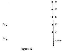

(a) If the observation was made in a ripple tank, describe:
(i) How the two sets of coherent waves were produced;
(ii) How the constructive and destructive interference are identified.
(b) Explain how the constructive interference C and the destructive interference D patterns are produced.
Date posted: May 26, 2017. Answers (1)
- Figure 15 shows an experiment arrangement for determining the wavelength of light, (Solved)
Figure 15 shows an experiment arrangement for determining the wavelength of light,
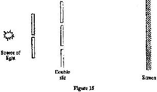
State and explain the difference in the patterns observed on the screen other than the difference in colour when the source of red light is replaced by a source of violet light.
Date posted: May 26, 2017. Answers (1)
- Fig. 6.1 shows the cross-section of a ripple tank full of water. A piece of cork floats on the surface of the water as shown.(Solved)
Fig. 6.1 shows the cross-section of a ripple tank full of water. A piece of cork floats on the surface of the water as shown. Fig.6 II shows the water surface viewed from above. A straight edge vibrator placed at the end A of ripple tank generates water waves, which travel towards end B as shown.

(i) Identify the type of waves generated in the water surface.
(ii) It is observed that as the waves pass the cork every 0.20 seconds. If the speed of the waves is 0.30ms-1, determine the frequency and wavelength of the waves at that point.
Date posted: May 26, 2017. Answers (1)
- In the Young's double slit experiment, and interference pattern of bright and dark fridges was formed as shown in Figure 1 by a light of wavelength coming from two narrow slits X and Y.(Solved)
In the Young's double slit experiment, and interference pattern of bright and dark fridges was formed as shown in Figure 1 by a light of wavelength coming from two narrow slits X and Y.
 (i) Explain how the dark and bright fringes are formed.
(ii) State and explain what would be observed on the screen if the slits X and Y were made large.
Date posted: May 26, 2017. Answers (1)
- In the Young's double slit experiment, and interference pattern of bright and dark fridges was formed as shown in Figure 1 by a light of wavelength coming from two narrow slits X and Y.(Solved)
In the Young's double slit experiment, and interference pattern of bright and dark fridges was formed as shown in Figure 1 by a light of wavelength coming from two narrow slits X and Y.

(i) Explain how the dark and bright fringes are formed.
(ii) State and explain what would be observed on the screen if the slits X and Y were made large.
Date posted: May 26, 2017. Answers (1)
- Fig. 11 shows a double slit placed in front of a source, S, of waves. A director D is placed beyond the slits, such that its position can be adjusted along the line XY. (Solved)
Fig. 11 shows a double slit placed in front of a source, S, of waves. A director D is placed beyond the slits, such that its position can be adjusted along the line XY.

State with a reason, what the detector records along XY.
Date posted: May 26, 2017. Answers (1)