Centripetal force, f = mv2r, where f = force, m = mass, v = velocity and r = radius, At B the radius, r is small hence the centripetal force f required is high. Since mass and velocity are constant, the car may slide off.
johnmulu answered the question on June 2, 2017 at 05:46
- Figure 16, shows a graph of magnification against object distance, for an object placed in front of a lens of focal length 20 cm. (Solved)
cFigure 16, shows a graph of magnification against object distance, for an object placed in front of a lens of focal length 20 cm.

Using the graph;
(i) State the effect on the size of the image when the object distance is increased from 25 cm.
(ii) Determine the distance between the object and the lens when the image is same size as the object.
(iii) Determine the image distance when the object distance is 25 cm.
Date posted: June 2, 2017. Answers (1)
- The figure 4 shows the diagram of set-up to investigate the variation of centripetal force with the radius, r, of the circle in which a body rotates. (Solved)
The figure 4 shows the diagram of set-up to investigate the variation of centripetal force with the radius, r, of the circle in which a body rotates.
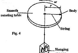
Describe how the set-up can be used to carry out the investigation
Date posted: June 2, 2017. Answers (1)
- In an experiment, a pin a converging lens and plane mirror are arranged as shown in Figure 4.(Solved)
In an experiment, a pin a converging lens and plane mirror are arranged as shown in Figure 4. The distance between the pin and the plane mirror is L cm while the distance between the lens and the plane mirror is q cm. The position of the pin is adjusted until its tip coincides with its real image.
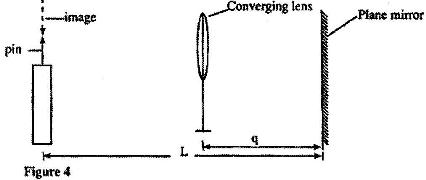
State the focal length of the lens.
Date posted: May 29, 2017. Answers (1)
- Figure 7 shows how rays from a distant and a near object are focused inside a human eye with a certain defect. (Solved)
Figure 7 shows how rays from a distant and a near object are focused inside a human eye with a certain defect.
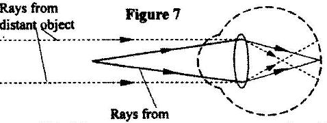
Name the defect and state the cause of this defect.
Date posted: May 29, 2017. Answers (1)
- Figure 12 shows the features of a simple camera. (Solved)
Figure 12 shows the features of a simple camera.
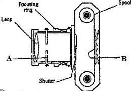
(i) Name the parts labeled A and B.
(ii) A still object is placed at a certain distance from the camera. Explain the adjustments necessary for a clear image of the object to be formed.
(iii) State the functions of the shutter and the parts labeled A and B
Date posted: May 29, 2017. Answers (1)
- Figure 8 shows an experimental set-up consisting of a mounted lens L, a screen, S, a meter rule and a candle. (Solved)
Figure 8 shows an experimental set-up consisting of a mounted lens L, a screen, S, a meter rule and a candle.
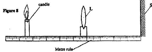
(i) Describe how the set-up may be used to determine the focal length, f, of the lens.
(ii) State the reason why the set-up would not work if the lens were replaced with a diverging lens.
Date posted: May 29, 2017. Answers (1)
- The diagram in Figure 3 shows a certain eye defect. (Solved)
The diagram in Figure 3 shows a certain eye defect.
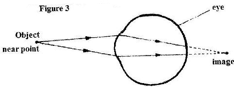
Name the defect.
Date posted: May 29, 2017. Answers (1)
- The pressure acting on a gas in a cylinder was changed steadily while the temperature of the(Solved)
The pressure acting on a gas in a cylinder was changed steadily while the temperature of the gas was maintained constant. The value of volume V of the gas was measured for various values of pressure. The graph in Figure 11 shows the relation between the pressure P, and the reciprocal of volume, 1V
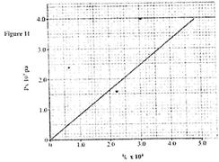
(i) Suggest how the temperature of the gas could be kept constant.
(ii) What physical quantity does K represent?
(iii) State one precaution you would take when performing such an experiment.
Date posted: May 29, 2017. Answers (1)
- Figure 11 shows an insulated cylinder fitted with a pressure gauge, a heating coil and a frictionless piston of cross-sectional area 100 cm2.
(Solved)
Figure 11 shows an insulated cylinder fitted with a pressure gauge, a heating coil and a frictionless piston of cross-sectional area 100 cm2.
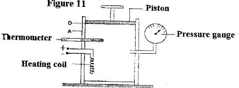
While the piston is at position O, the pressure of the enclosed gas is 10 Ncm-2 at a temperature of 27oC. when a 10 kg mass is placed on the piston, it comes to rest at position A without the temperature of the gas.
(i) Determine the new reading on the pressure gauge.
(ii) State with a reason how the value obtained in (i) compares with the initial pressure.
Date posted: May 29, 2017. Answers (1)
- The tube is now held in a vertical position with the open end facing upwards as shown in figure 8. (Solved)
The tube is now held in a vertical position with the open end facing upwards as shown in figure 8.

Determine:
(i) The pressure of the enclosed air.
(ii) The length (l) of the enclosed air column.
Date posted: May 29, 2017. Answers (1)
- Figure 7 shows a horizontal tube containing air trapped by a mercury thread of length 24 cm. The length of the enclosed air column is 15 cm, The atmospheric pressure is 76 cmHg. (Solved)
Figure 7 shows a horizontal tube containing air trapped by a mercury thread of length 24 cm. The length of the enclosed air column is 15 cm, The atmospheric pressure is 76 cmHg.

State the pressure of the enclosed air.
Date posted: May 29, 2017. Answers (1)
- Figure 6 shows a graph of volume against temperature for a given mass of gas. (Solved)
Figure 6 shows a graph of volume against temperature for a given mass of gas.
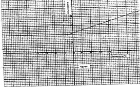
Use the graph to determine the absolute zero temperature in oC
Date posted: May 29, 2017. Answers (1)
- An air bubble is released at the bottom of a tall jar containing a liquid(Solved)
An air bubble is released at the bottom of a tall jar containing a liquid. The height of the liquid column is 80 cm. The volume of the bubble increases from 0.5 cm3 at the bottom of the liquid to 1.15 cm3 at the top. Figure 11 shows the variation of pressure, P, on the bubble with the reciprocal of volume, 15, as it rises in the liquid.
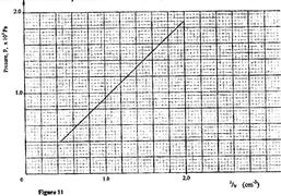
(i) State the reason why the volume increases as the bubble rises in the liquid column.
(ii) From the graph, determine the pressure on the bubble:
(I) at the bottom of the liquid column;
(II) at the top of liquid column
Date posted: May 29, 2017. Answers (1)
- The graph in Figure 11 shows the relationship between volume and temperature for the experiment. (Solved)
The graph in Figure 11 shows the relationship between volume and temperature for the experiment.
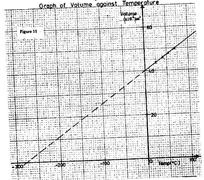
(i) What was the volume of the gas at 0o?
(ii) At what temperature would the volume of the gas be zero?
(iii) Explain why the temperature in part (ii) above cannot be achieved.
Date posted: May 29, 2017. Answers (1)
- Figure 10 shows a set up to investigate the relationship between temperature and volume for a certain gas. (Solved)
Figure 10 shows a set up to investigate the relationship between temperature and volume for a certain gas.
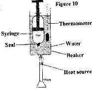
State two factors that are kept constant, in order to determine the relationship.
Date posted: May 29, 2017. Answers (1)
- The graph in figure 7 shows the relationship between the pressure and temperature for an ideal gas. use the information in the figure to answer questions (a)and(b). (Solved)
The graph in figure 7 shows the relationship between the pressure and temperature for an ideal gas. use the information in the figure to answer questions (a)and(b).
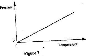
(a) State the unit of the horizontal axis.
(b) Write a statement of the gas law represented by the relationship.
Date posted: May 29, 2017. Answers (1)
- The pressure acting on a gas in a container was changed steadily while the temperature(Solved)
The pressure acting on a gas in a container was changed steadily while the temperature of the gas was maintained constant. The value of volume V of the gas was measured for various values of pressure. The graph in Figure 9 shows the relation between the pressure, P, and reciprocal of volume, \fracf1V
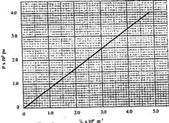
(i) Suggest how the temperature of the gas could be kept constant.
(ii) What physical quantity does k represent?
(iii) State one precaution you would take when performing such an experiment.
Date posted: May 29, 2017. Answers (1)
- Figure 6 shows a simple set up for pressure law apparatus. (Solved)
Figure 6 shows a simple set up for pressure law apparatus.
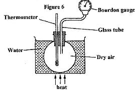
Describe how the apparatus may be used to verify pressure law.
Date posted: May 29, 2017. Answers (1)
- Figure 7 shows an experiment set-up that may be used to investigate one of the laws. The glass tube has a uniform bore and it is graduated in millimeters.(Solved)
Figure 7 shows an experiment set-up that may be used to investigate one of the laws. The glass tube has a uniform bore and it is graduated in millimeters.
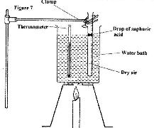
(i) Describe how the experiment is carried out and explain how the results obtained verify the law.
(ii) State two limitations of the set-up.
Date posted: May 29, 2017. Answers (1)
- Figure 5 shows a set up that ,a set up that may be used to verify Charles' law.(Solved)
Figure 5 shows a set up that ,a set up that may be used to verify Charles' law.
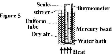
(i) State the measurements that should be taken in the experiment.
(ii) What is the purpose of the water bath?
Date posted: May 29, 2017. Answers (1)