(i) Tension is the spring supporting the object
(ii) There's change in the direction of instantaneous velocity at various points along the circular path.
(iii) reading of spring balance = centripetal force
= mv2r = 0.5×8××82 = 16 N
johnmulu answered the question on June 2, 2017 at 11:49
- Figure 10 shows the path of an object of mass m attached to a string of length r when whirled in a vertical circle at a constant speed V. A is the highest point on its path.(Solved)
Figure 10 shows the path of an object of mass m attached to a string of length r when whirled in a vertical circle at a constant speed V. A is the highest point on its path.

State the forces that provide the centripetal force on the object when it is at point A.
Date posted: June 2, 2017. Answers (1)
- Figure 11 shows a stone attached to the end of a string moving in a horizontal circle with a uniform speed of 2 ms-1. When the stone reaches point X on the circle, the string breaks
(Solved)
Figure 11 shows a stone attached to the end of a string moving in a horizontal circle with a uniform speed of 2 ms-1. When the stone reaches point X on the circle, the string breaks

State the magnitude of the velocity after the string breaks. and give a reason
Date posted: June 2, 2017. Answers (1)
- Three masses are placed on a rotating table at distances 6 cm, 9 cm and 12 cm respectively (Solved)
Three masses are placed on a rotating table at distances 6 cm, 9 cm and 12 cm respectively from the centre of rotation. When the frequency of rotation is varied, it is noted that each mass slides off at a different frequency of rotation of the table. Table 1 shows the frequency at which each mass slides off.
 d on the table before placing the masses. Explain the effect of this on the frequency at which each mass slides off.
Date posted: June 2, 2017. Answers (1)
- Figure 12 shows masses A, B and C placed at different points on a rotating table. The angular velocity, of the table can be varied. (Solved)
Figure 12 shows masses A, B and C placed at different points on a rotating table. The angular velocity, of the table can be varied.

State two factors that determine whether a particular mass slides off the table or not.
Date posted: June 2, 2017. Answers (1)
- Figure 6 shows the path taken by a matatu traveling on a horizontal ground (a winding road). (Solved)
Figure 6 shows the path taken by a matatu traveling on a horizontal ground (a winding road).

The speed of the matatu is constant. Identify with reason the point along the path which a load placed loosely on the rack (carrier) of the matatu is most likely to roll off.
Date posted: June 2, 2017. Answers (1)
- A child of mass 20 kg sits on a swing of length 4 m and swings through a vertical height of 0.9 m as shown in figure 2. (Solved)
A child of mass 20 kg sits on a swing of length 4 m and swings through a vertical height of 0.9 m as shown in figure 2.

Determine:
(i) Speed of the child when passing through the lowest point.
(ii) Force exerted on the child by the seat of the swing when passing through the lowest point.
Date posted: June 2, 2017. Answers (1)
- Figure 8 shows a container with small holes at the bottom in which wet clothes have been put. When the container is whirled in air at high speed as shown, it is observed that the clothes dry faster. (Solved)
Figure 8 shows a container with small holes at the bottom in which wet clothes have been put. When the container is whirled in air at high speed as shown, it is observed that the clothes dry faster.

Explain how the rotation of the container causes the clothes to dry faster.
Date posted: June 2, 2017. Answers (1)
- Figure 8 shows a car of mass M moving along a curved part of the road with a constant speed. (Solved)
Figure 8 shows a car of mass M moving along a curved part of the road with a constant speed.

Explain the fact that the car is more likely to slide at B than at A if the speed is not changed.
Date posted: June 2, 2017. Answers (1)
- Figure 16, shows a graph of magnification against object distance, for an object placed in front of a lens of focal length 20 cm. (Solved)
cFigure 16, shows a graph of magnification against object distance, for an object placed in front of a lens of focal length 20 cm.

Using the graph;
(i) State the effect on the size of the image when the object distance is increased from 25 cm.
(ii) Determine the distance between the object and the lens when the image is same size as the object.
(iii) Determine the image distance when the object distance is 25 cm.
Date posted: June 2, 2017. Answers (1)
- The figure 4 shows the diagram of set-up to investigate the variation of centripetal force with the radius, r, of the circle in which a body rotates. (Solved)
The figure 4 shows the diagram of set-up to investigate the variation of centripetal force with the radius, r, of the circle in which a body rotates.
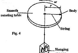
Describe how the set-up can be used to carry out the investigation
Date posted: June 2, 2017. Answers (1)
- In an experiment, a pin a converging lens and plane mirror are arranged as shown in Figure 4.(Solved)
In an experiment, a pin a converging lens and plane mirror are arranged as shown in Figure 4. The distance between the pin and the plane mirror is L cm while the distance between the lens and the plane mirror is q cm. The position of the pin is adjusted until its tip coincides with its real image.
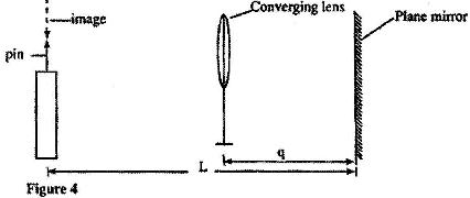
State the focal length of the lens.
Date posted: May 29, 2017. Answers (1)
- Figure 7 shows how rays from a distant and a near object are focused inside a human eye with a certain defect. (Solved)
Figure 7 shows how rays from a distant and a near object are focused inside a human eye with a certain defect.
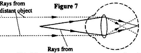
Name the defect and state the cause of this defect.
Date posted: May 29, 2017. Answers (1)
- Figure 12 shows the features of a simple camera. (Solved)
Figure 12 shows the features of a simple camera.
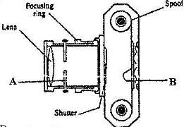
(i) Name the parts labeled A and B.
(ii) A still object is placed at a certain distance from the camera. Explain the adjustments necessary for a clear image of the object to be formed.
(iii) State the functions of the shutter and the parts labeled A and B
Date posted: May 29, 2017. Answers (1)
- Figure 8 shows an experimental set-up consisting of a mounted lens L, a screen, S, a meter rule and a candle. (Solved)
Figure 8 shows an experimental set-up consisting of a mounted lens L, a screen, S, a meter rule and a candle.
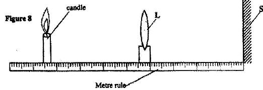
(i) Describe how the set-up may be used to determine the focal length, f, of the lens.
(ii) State the reason why the set-up would not work if the lens were replaced with a diverging lens.
Date posted: May 29, 2017. Answers (1)
- The diagram in Figure 3 shows a certain eye defect. (Solved)
The diagram in Figure 3 shows a certain eye defect.
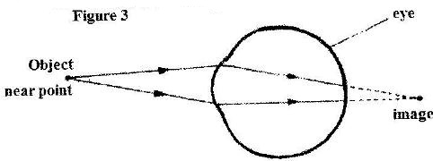
Name the defect.
Date posted: May 29, 2017. Answers (1)
- The pressure acting on a gas in a cylinder was changed steadily while the temperature of the(Solved)
The pressure acting on a gas in a cylinder was changed steadily while the temperature of the gas was maintained constant. The value of volume V of the gas was measured for various values of pressure. The graph in Figure 11 shows the relation between the pressure P, and the reciprocal of volume, 1V
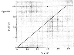
(i) Suggest how the temperature of the gas could be kept constant.
(ii) What physical quantity does K represent?
(iii) State one precaution you would take when performing such an experiment.
Date posted: May 29, 2017. Answers (1)
- Figure 11 shows an insulated cylinder fitted with a pressure gauge, a heating coil and a frictionless piston of cross-sectional area 100 cm2.
(Solved)
Figure 11 shows an insulated cylinder fitted with a pressure gauge, a heating coil and a frictionless piston of cross-sectional area 100 cm2.
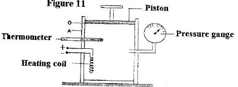
While the piston is at position O, the pressure of the enclosed gas is 10 Ncm-2 at a temperature of 27oC. when a 10 kg mass is placed on the piston, it comes to rest at position A without the temperature of the gas.
(i) Determine the new reading on the pressure gauge.
(ii) State with a reason how the value obtained in (i) compares with the initial pressure.
Date posted: May 29, 2017. Answers (1)
- The tube is now held in a vertical position with the open end facing upwards as shown in figure 8. (Solved)
The tube is now held in a vertical position with the open end facing upwards as shown in figure 8.

Determine:
(i) The pressure of the enclosed air.
(ii) The length (l) of the enclosed air column.
Date posted: May 29, 2017. Answers (1)
- Figure 7 shows a horizontal tube containing air trapped by a mercury thread of length 24 cm. The length of the enclosed air column is 15 cm, The atmospheric pressure is 76 cmHg. (Solved)
Figure 7 shows a horizontal tube containing air trapped by a mercury thread of length 24 cm. The length of the enclosed air column is 15 cm, The atmospheric pressure is 76 cmHg.

State the pressure of the enclosed air.
Date posted: May 29, 2017. Answers (1)
- Figure 6 shows a graph of volume against temperature for a given mass of gas. (Solved)
Figure 6 shows a graph of volume against temperature for a given mass of gas.
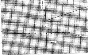
Use the graph to determine the absolute zero temperature in oC
Date posted: May 29, 2017. Answers (1)