(i) To allow all radiations to penetrate
(ii) On entering the tube, the radiation ionizes argon gas. The positive ions flows towards the cathode and negative ions towards the anode. This creates potential difference that results to flow of pulse current.
(iii) To absorb the energy of positive ions before they cause secondary electron emission.
johnmulu answered the question on June 6, 2017 at 08:22
-
Figure 8 shows ultra-violet light striking a polished zinc plate placed on a negatively charged gold-leaf electroscope.
(Solved)
Figure 8 shows ultra-violet light striking a polished zinc plate placed on a negatively charged gold-leaf electroscope.

Explain the following observations.
(i) The leaf of the electroscope falls.
(ii) When the same experiment was repeated with a positively charged electroscope the leaf did not fall
Date posted:
June 6, 2017
.
Answers (1)
-
Explain how land and sea breeze occurs
(Solved)
Explain how land and sea breeze occurs.
Date posted:
June 6, 2017
.
Answers (1)
-
Figure 18 shows the parts of an x-ray tube.
(Solved)
Figure 18 shows the parts of an x-ray tube.

(a) Explain why:
(i) A potential difference is applied to the filament.
(ii) A high potential difference is applied between a cathode and the anode.
(iii) Most of the tube is surrounded by lead.
(b) State how the resulting x -rays are affected by increasing the potential difference between the anode and the cathode.
Date posted:
June 6, 2017
.
Answers (1)
-
Figure 13 shows the features of an X-ray tube.
(Solved)
Figure 13 shows the features of an X-ray tube.

(i) Name the parts labeled A and B.
(ii) Explain how a change in the potential across PQ changes the intensity of the X -rays produced in the tube.
(iii) During the operation of the tube, the target becomes very hot. Explain how this heat is caused.
(iv) What property of lead makes it suitable for use as shielding material?
Date posted:
June 6, 2017
.
Answers (1)
-
Figure 10 shows the main features of a cathode ray oscilloscope (CRO).
(Solved)
Figure 10 shows the main features of a cathode ray oscilloscope (CRO).

(i) Name the part labeled M and N.
(ii) Explain how electrons are produced in the tube.
(iii) State why the tube is highly evacuated.
Date posted:
June 6, 2017
.
Answers (1)
-
Figure 3 shows the main features of a cathode ray tube (CRT) of a cathode ray oscilloscope (CRO).
(Solved)
Figure 3 shows the main features of a cathode ray tube (CRT) of a cathode ray oscilloscope (CRO).

(i) Describe how the electrons are produced in the tube.
(ii) State and explain the function of the grid.
(iii) State what would be observed on the screen if an a.c voltage is connected across the y-plates.
Date posted:
June 5, 2017
.
Answers (1)
-
Figure 15, shows two coils A and B placed close to each other. A is connected to a steady D.C. Supply and a switch, B is connected to a sensitive galvanometer.
(Solved)
Figure 15, shows two coils A and B placed close to each other. A is connected to a steady D.C. Supply and a switch, B is connected to a sensitive galvanometer.

(i) The switch is now closed. State the observations made on the galvanometer.
(ii) Explain what would be observed if the switch is then open.
Date posted:
June 5, 2017
.
Answers (1)
-
Figure 11 shows a test-tube whose cross-sectional area is 2 cm2 partially filled with lead shot floating vertically in water.
(Solved)
Figure 11 shows a test-tube whose cross-sectional area is 2 cm2 partially filled with lead shot floating vertically in water.

(i) Determine the: volume of the water displaced;
(ii) Determine weight of water displaced.
(iii) State the combined weight of the test-tube and the lead shot.
Date posted:
June 5, 2017
.
Answers (1)
-
Figure 13 shows a hydrometer with a thin stem floating in water in a beaker.
(Solved)
Figure 13 shows a hydrometer with a thin stem floating in water in a beaker.

State with a reason what is observed on the hydrometer when the temperature of the water is raised.
Date posted:
June 5, 2017
.
Answers (1)
-
Figure 13 shows a log of wood of mass 20 kg submerged in water in a pond and held in position by a string fixed to the bottom of the pond.
(Solved)
Figure 13 shows a log of wood of mass 20 kg submerged in water in a pond and held in position by a string fixed to the bottom of the pond.

Given that the density of water is 1000 kgm -3 and that of wood is 800 kgm -3, determine the;
(i) Volume of the log.
(ii) Upthrust of the log.
(iii) Tension in the string.
Date posted:
June 5, 2017
.
Answers (1)
-
The system in Figure below is in equilibrium.
(Solved)
The system in Figure below is in equilibrium.

When temperature of the water is raised the system is observed to tilt to the right. State the reason for this observation.
Date posted:
June 5, 2017
.
Answers (1)
-
Figure 14 shows a cork floating on water and held to the bottom of the beaker by a thin thread.
(Solved)
Figure 14 shows a cork floating on water and held to the bottom of the beaker by a thin thread.

(i) Name the forces acting on the cork
(ii) Describe how each of the forces mentioned in (i) above changes when water is added into the beaker until it fills up.
Date posted:
June 5, 2017
.
Answers (1)
-
Figure 13 shows a simple hydrometer.
(Solved)
Figure 13 shows a simple hydrometer.

(i) State the purpose of the lead shots in the glass bulb.
(ii) How would the hydrometer be made more sensitive?
(iii) Describe how the hydrometer is calibrated to measure relative density.
Date posted:
June 5, 2017
.
Answers (1)
-
Figure 8 shows a container with small holes at the bottom in which wet clothes have been put. When the container is whirled in air at high speed as shown, it is observed that the clothes dry faster.
(Solved)
Figure 8 shows a container with small holes at the bottom in which wet clothes have been put. When the container is whirled in air at high speed as shown, it is observed that the clothes dry faster.

Explain how the rotation of the container causes the clothes to dry faster.
Date posted:
June 2, 2017
.
Answers (1)
-
Figure 8 shows a car of mass M moving along a curved part of the road with a constant speed.
(Solved)
Figure 8 shows a car of mass M moving along a curved part of the road with a constant speed.

Explain the fact that the car is more likely to slide at B than at A if the speed is not changed.
Date posted:
June 2, 2017
.
Answers (1)
-
Figure 16, shows a graph of magnification against object distance, for an object placed in front of a lens of focal length 20 cm.
(Solved)
cFigure 16, shows a graph of magnification against object distance, for an object placed in front of a lens of focal length 20 cm.

Using the graph;
(i) State the effect on the size of the image when the object distance is increased from 25 cm.
(ii) Determine the distance between the object and the lens when the image is same size as the object.
(iii) Determine the image distance when the object distance is 25 cm.
Date posted:
June 2, 2017
.
Answers (1)
-
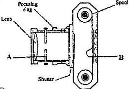
Figure 12 shows the features of a simple camera.
(Solved)
Figure 12 shows the features of a simple camera.

(i) Name the parts labeled A and B.
(ii) A still object is placed at a certain distance from the camera. Explain the adjustments necessary for a clear image of the object to be formed.
(iii) State the functions of the shutter and the parts labeled A and B
Date posted:
May 29, 2017
.
Answers (1)
-
Figure 7 shows a horizontal tube containing air trapped by a mercury thread of length 24 cm. The length of the enclosed air column is 15 cm, The atmospheric pressure is 76 cmHg.
(Solved)
Figure 7 shows a horizontal tube containing air trapped by a mercury thread of length 24 cm. The length of the enclosed air column is 15 cm, The atmospheric pressure is 76 cmHg.

State the pressure of the enclosed air.
Date posted:
May 29, 2017
.
Answers (1)
-
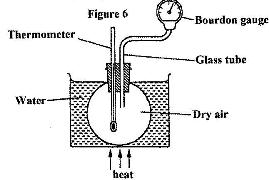
Figure 6 shows a simple set up for pressure law apparatus.
(Solved)
Figure 6 shows a simple set up for pressure law apparatus.

Describe how the apparatus may be used to verify pressure law.
Date posted:
May 29, 2017
.
Answers (1)
-
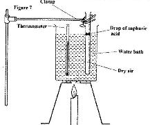
Figure 7 shows an experiment set-up that may be used to investigate one of the laws. The glass tube has a uniform bore and it is graduated in millimeters.
(Solved)
Figure 7 shows an experiment set-up that may be used to investigate one of the laws. The glass tube has a uniform bore and it is graduated in millimeters.

(i) Describe how the experiment is carried out and explain how the results obtained verify the law.
(ii) State two limitations of the set-up.
Date posted:
May 29, 2017
.
Answers (1)