- Explain the following terms and state their S.I units
(i) Wavelength
(ii) Amplitude
(iii) Periodic time
(iv) Frequency(Solved)
Explain the following terms and state their S.I units
(i) Wavelength
(ii) Amplitude
(iii) Periodic time
(iv) Frequency
Date posted: March 26, 2019. Answers (1)
- Define the refractive index of a substance(Solved)
Define the refractive index of a substance.
Date posted: March 26, 2019. Answers (1)
- The following reaction is part of reactive series.(Solved)
The following reaction is part of reactive series.

Identify the radiation Q and determine the values of B and C.
Date posted: March 26, 2019. Answers (1)
- A source generates 40 waves in a second. If the wavelength is 8.5 cm. Calculate the time taken to reach a wall 102 m from...(Solved)
A source generates 40 waves in a second. If the wavelength is 8.5 cm. Calculate the time taken to reach a wall 102 m from the source.
Date posted: March 26, 2019. Answers (1)
- State one effect that would be observed when water waves pass from deep to shallow water.(Solved)
State one effect that would be observed when water waves pass from deep to shallow water.
Date posted: March 26, 2019. Answers (1)
- QFM broadcasts at 96.4 MHz, determine the wavelength of the radio broadcast.
(Speed of light, C=3.0×10⁸m/s).
(Solved)
QFM broadcasts at 96.4 MHz, determine the wavelength of the radio broadcast.
(Speed of light, C=3.0×10⁸m/s).
Date posted: March 26, 2019. Answers (1)
- Figure below shows the displacement – time graph for a certain wave(Solved)
Figure below shows the displacement – time graph for a certain wave

Determine the frequency of the wave?
Date posted: March 26, 2019. Answers (1)
- An optical pin 20mm high is placed horizontally on the principal axis of a convex mirror of focal length 6cm as shown in the figure...(Solved)
An optical pin 20mm high is placed horizontally on the principal axis of a convex mirror of focal length 6cm as shown in the figure below.

X is south pole and Y is north pole. Indicate the terminal of A and B on the diagram.
Date posted: March 26, 2019. Answers (1)
- Distinguish between ductile end and brittle material(Solved)
Distinguish between ductile end and brittle material
Date posted: March 26, 2019. Answers (1)
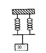
- Two identical springs of spring constant 3N/cm are used to support a load of 30N as shown. Determine the extension of each spring.(Solved)
Two identical springs of spring constant 3N/cm are used to support a load of 30N as shown. Determine the extension of each spring.

Date posted: March 26, 2019. Answers (1)
- An experiment was performed to find out how the length L of a spiral spring varies with the compression force, F. The figure below shows...(Solved)
An experiment was performed to find out how the length L of a spiral spring varies with the compression force, F. The figure below shows the variation.

(i) Draw a diagram of a possible set up of the apparatus
(ii) Over which range of the force does the spring obey Hooker’s law?
(iii) Suggest a reason for the shape of the graph between 40N and 60N
Date posted: March 26, 2019. Answers (1)
- The figure below shows a metallic rod placed in a coil connected to battery terminals A and B.(Solved)
The figure below shows a metallic rod placed in a coil connected to battery terminals A and B.

X is south pole and Y is north pole. Indicate the terminal of A and B on the diagram.
Date posted: March 26, 2019. Answers (1)
- State FOUR reasons why the efficiency of an electric motor is always less than 100%(Solved)
State FOUR reasons why the efficiency of an electric motor is always less than 100%
Date posted: March 26, 2019. Answers (1)
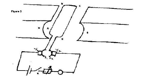
- Figure below shows a D.C electric motor.(Solved)
Figure below shows a D.C electric motor.

(a) Name the parts labeled X1 and X2 and state their functions.
(b) What is the purpose of parts labeled Y1 and Y2?
(c) When the switch k is closed state the forces acting on the sides of the coil and the direction of movement of the coil
(d) What can be done to increase the speed of rotation of the motor?
Date posted: March 26, 2019. Answers (1)
- An un-insulated copper wire XY lies over the fixed wire A and B connected to a battery when the key in the circuit is closed,...(Solved)
An un-insulated copper wire XY lies over the fixed wire A and B connected to a battery when the key in the circuit is closed, the wire XY experiences a force.

(i) In which direction does the wire XY- experience the force?
(ii) How do you determine the direction in (i) above
(iii) When is the force on the wire XY greatest?
(iv) What is the effect of reversing both the magnetic field and direction of flow of current?
(v) State TWO factors by which the force on XY can be decreased
Date posted: March 26, 2019. Answers (1)
- An iron rod XY is placed inside a coil of wire. What type of magnetic pole is induced at the end x when the current...(Solved)
An iron rod XY is placed inside a coil of wire. What type of magnetic pole is induced at the end x when the current flows through the coil?

Date posted: March 26, 2019. Answers (1)
- Figure below shows an incomplete circuit of an electromagnet. Complete the circuit between X and Y by drawing the windings on the two arms of...(Solved)
Figure below shows an incomplete circuit of an electromagnet. Complete the circuit between X and Y by drawing the windings on the two arms of the core such that A and B are both North poles when switch S is closed. Indicate the direction of the current on the windings drawn.

Date posted: March 26, 2019. Answers (1)
- An armature composed of turns of insulated copper wire wound on a laminated soft- iron core is rotated in a magnetic field to generate an...(Solved)
An armature composed of turns of insulated copper wire wound on a laminated soft- iron core is rotated in a magnetic field to generate an e.m.f. Use this information to answer the following questions.
(a) State two factors other than the speed of rotation that affect the magnitude of the e.m.f generated.
(b) State the reason why soft- iron is laminated.
Date posted: March 26, 2019. Answers (1)
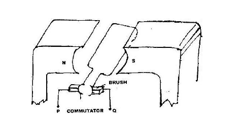
- Figure below shows an electric generator. The points P and Q are connected to a Cathode Ray Oscilloscope (CRO).(Solved)
Figure below shows an electric generator. The points P and Q are connected to a Cathode Ray Oscilloscope (CRO).

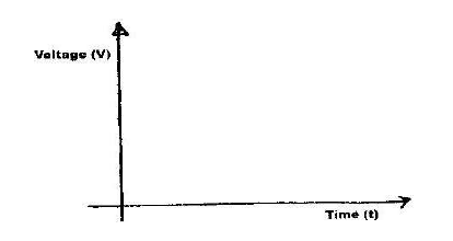
Sketch on the axes provided the graph of the voltage output as seen on the CRO, given that when t= 0, the coil is at the position shown in the figure.

Date posted: March 26, 2019. Answers (1)
- State characteristics of an image observed in a concave mirror when the object is between the focal point and the mirror.(Solved)
State characteristics of an image observed in a concave mirror when the object is between the focal point and the mirror.
Date posted: March 26, 2019. Answers (1)