Treatment of cancer, tumors
sharon kalunda answered the question on April 5, 2019 at 13:23
- The figure shows a cross- section of a bicycle dynamo. The wheel is connected by an axle
to a permanent cylindrical magnet and is rotated by...(Solved)
The figure shows a cross- section of a bicycle dynamo. The wheel is connected by an axle
to a permanent cylindrical magnet and is rotated by the bicycle tyre

i) Explain why the bulb lights
ii) How can the bulb be made brighter
Date posted: April 5, 2019. Answers (1)
- A transformer is designed as shown in the figure below. If the primary coil has 2400 turns and
the secondary has 200 turns calculate the p.d...(Solved)
A transformer is designed as shown in the figure below. If the primary coil has 2400 turns and
the secondary has 200 turns calculate the p.d across BC assuming there are no energy losses in
the transformer

Date posted: April 5, 2019. Answers (1)
- What would be observed in the diagram below when switch S is closed, B1 and B2 are
identical torch bulbs(Solved)
What would be observed in the diagram below when switch S is closed, B1 and B2 are
identical torch bulbs

Date posted: April 5, 2019. Answers (1)
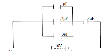
- The diagram below shows an arrangement of capacitors in a circuit(Solved)
The diagram below shows an arrangement of capacitors in a circuit

Determine the total charge in the circuit
Date posted: April 5, 2019. Answers (1)
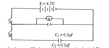
- Figure shows a circuit where a battery of emf 4.5V, switches A and B, two capacitors.C1= 0.3 µF and C2 = 0.5 µF and a...(Solved)
Figure shows a circuit where a battery of emf 4.5V, switches A and B, two capacitors.C1= 0.3 μF and C2 = 0.5 μF and a voltmeter are connected.

a) Determine the charge on C1 when switch A is closed and switch B is open
b) What is the effective capacitance CT when both switches A and B are closed?
Date posted: April 5, 2019. Answers (1)
- In an attempt to establish the relationship between current through a junction diode and the p.d
across it, a student connected a diode to an e.m.f...(Solved)
In an attempt to establish the relationship between current through a junction diode and the p.d
across it, a student connected a diode to an e.m.f source as in figure below:-

(a) State whether the diode is forward biased or reverse biased
(b) Briefly describe how she obtained her readings
Date posted: April 5, 2019. Answers (1)
- State the purpose of introducing an impurity in a semi conductor.(Solved)
State the purpose of introducing an impurity in a semi conductor.
Date posted: April 5, 2019. Answers (1)
- Figure below shows a diagram of an n – p – n transistor.(Solved)
Figure below shows a diagram of an n – p – n transistor.

Complete the diagram by showing the connections of two batteries suitable for biasing the
transistor in the common- emitter mode.
Date posted: April 5, 2019. Answers (1)
- Three identical bulbs are connected in series with a battery of dry cells. At first the bulbs
shine brightly but gradually become dimmer. Using the same...(Solved)
Three identical bulbs are connected in series with a battery of dry cells. At first the bulbs
shine brightly but gradually become dimmer. Using the same cells, explain how you
would increase the brilliance of the bulbs
Date posted: April 5, 2019. Answers (1)
- A girl opened up a used up dry cell and found the following:
i) The zinc casing was ‘eaten away’
ii) The cell was watery(Solved)
A girl opened up a used up dry cell and found the following:
i) The zinc casing was ‘eaten away’
ii) The cell was watery
Name the cell defect
Date posted: April 5, 2019. Answers (1)
- State one reason why colour televisions have a higher power rating than black and white
televisions(Solved)
State one reason why colour televisions have a higher power rating than black and white
televisions
Date posted: April 5, 2019. Answers (1)
- The figure shows a simple cell made of copper and zinc electrodes dipped in dilute
sulphuric acid(Solved)
The figure shows a simple cell made of copper and zinc electrodes dipped in dilute
sulphuric acid.

a) Identify the cathode
b) If a voltmeter is connected across the rods the reading is observed to reduce with time.
State two causes of this observation
Date posted: April 5, 2019. Answers (1)
- The figure below shows the set up for a simple cell.(Solved)
The figure below shows the set up for a simple cell.

a) Name the Electrode A and the solution B
b) State two reasons why the bulb goes off after a short time
Date posted: April 5, 2019. Answers (1)
- Distinguish between Topping and Dopping(Solved)
Distinguish between Topping and Dopping
Date posted: April 5, 2019. Answers (1)
- Figure shows a voltmeter connected across the cell. The voltmeter reads 1.5V when the
switch S, is open and 1.25V when the switch is closed.(Solved)
Figure shows a voltmeter connected across the cell. The voltmeter reads 1.5V when the
switch S, is open and 1.25V when the switch is closed.

i) What is the e.m.f of the cell?
ii) What is the terminal voltage of the cell?
iii) Calculate the internal resistance of the cell
Date posted: April 5, 2019. Answers (1)
- Distinguish between a p- type and an n- type extrinsic semiconductors(Solved)
Distinguish between a p- type and an n- type extrinsic semiconductors
Date posted: April 5, 2019. Answers (1)
- Explain why eight 1.5V cells arranged in series to give a total of 12V cannot be used to start
a car. But car battery of 12V...(Solved)
Explain why eight 1.5V cells arranged in series to give a total of 12V cannot be used to start
a car. But car battery of 12V starts a car
Date posted: April 5, 2019. Answers (1)
- Figure below shows a circle with two diodes P and Q and a cell:-(Solved)
Figure below shows a circle with two diodes P and Q and a cell:-

Explain the observation which would be made if S is closed
Date posted: April 5, 2019. Answers (1)
- With the time base switched on; the following trace was obtained on the screen of a CRO as
shown in the figure below:(Solved)
With the time base switched on; the following trace was obtained on the screen of a CRO as
shown in the figure below:

Draw a circuit diagram that can be used to produce the wave above
Date posted: April 5, 2019. Answers (1)
- Explain how conductivity of a semiconductor changes with increase in temperature(Solved)
Explain how conductivity of a semiconductor changes with increase in temperature
Date posted: April 5, 2019. Answers (1)