- The figure shows a bar magnet FG being pushed into a coil connected to a centre zero galvanometer. The current induced in the coil is...(Solved)
The figure shows a bar magnet FG being pushed into a coil connected to a centre zero galvanometer. The current induced in the coil is shown.

State the polarity of F.
Date posted: May 29, 2019. Answers (1)
- State two differences between light waves and sound waves.(Solved)
State two differences between light waves and sound waves.
Date posted: May 29, 2019. Answers (1)
- The figure shows a transverse wave.
a) Calculate the frequency of the wave.
b) Sketch another wave on the same diagram that has double the frequency and...(Solved)
The figure shows a transverse wave.

a) Calculate the frequency of the wave.
b) Sketch another wave on the same diagram that has double the frequency and half the amplitude and label it
as m.
Date posted: May 29, 2019. Answers (1)
- The figure below shows a simple circuit breaker.
Explain briefly how it works.(Solved)
The figure below shows a simple circuit breaker.

Explain briefly how it works.
Date posted: May 29, 2019. Answers (1)
- One method of making a simple d.c motor more powerful is to wind the coil on a soft iron core. Explain how this
method increases the...(Solved)
One method of making a simple d.c motor more powerful is to wind the coil on a soft iron core. Explain how this
method increases the power of the motor.
Date posted: May 29, 2019. Answers (1)
- A student while investigating the focal length of a certain concave mirror, measured object and image distances
and drew a graph of 1/u against 1/v shown...(Solved)
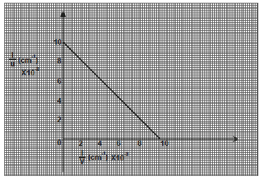
A student while investigating the focal length of a certain concave mirror, measured object and image distances
and drew a graph of 1/u against 1/v shown below.

From the graph, determine the focal length.
Date posted: May 29, 2019. Answers (1)
- The figure below shows an object O placed infront of a concave mirror.
a) Draw rays of light from the object to the mirror to show...(Solved)
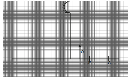
The figure below shows an object O placed infront of a concave mirror.
a) Draw rays of light from the object to the mirror to show how the image is formed.

b) State one
i) similarity between the image formed in (a) above and that formed by a plane mirror.
ii) application of the set up in (a) above.
Date posted: May 29, 2019. Answers (1)
- What is meant by the term “topping” as applied to a lead acid accumulator ?(Solved)
What is meant by the term “topping” as applied to a lead acid accumulator ?
Date posted: May 29, 2019. Answers (1)
- The figure below shows a gold leaf electroscope charged negatively.
State and explain what happens to the leaf when a negative charged rod is brought near...(Solved)
The figure below shows a gold leaf electroscope charged negatively.

State and explain what happens to the leaf when a negative charged rod is brought near the cap without touching it.
Date posted: May 29, 2019. Answers (1)
- The figure below shows a ray of light XY striking the mirror CD held at an angle of 1080 to mirror DE.Complete the path of...(Solved)
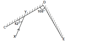
The figure below shows a ray of light XY striking the mirror CD held at an angle of 1080 to mirror DE.

Complete the path of the ray XY and state the final angle of reflection.
Date posted: May 29, 2019. Answers (1)
- The maximum wavelength of light required to cause photoelectric emission on a metal surface is 8.0×10⁻⁷. The metal surface is irradiated with light of freque4ncy...(Solved)
The maximum wavelength of light required to cause photoelectric emission on a metal surface is 8.0×10⁻⁷. The metal surface is irradiated with light of freque4ncy 8.5 × 10¹⁴ Hz. Determine
i) The threshold frequency.
ii) The work function of the metal in electron volts.
iii) The maximum kinetic energy of the electron.
iv The maximum velocity of the emitted electrons.
(Take 1ev = 1.6×10⁻¹⁹J, C=3.0×10⁸m/s, h=6.63×10⁻³⁴Js and mass of electron = 9.11 × 10⁻³¹kg)
Date posted: May 27, 2019. Answers (1)
- An electric iron of resistance 60 and an indicator of resistance 500 are connected in parallel to a 240V mains supply.
Find the power dissipated.(Solved)
An electric iron of resistance 60 and an indicator of resistance 500 are connected in parallel to a 240V mains supply.
Find the power dissipated.
Date posted: May 27, 2019. Answers (1)
- The following diagram represents a reverse bias characteristics of p-n junction.
i) Draw a circuit diagram of a reverse biased p-n junction.
ii) From the graph, some...(Solved)
The following diagram represents a reverse bias characteristics of p-n junction.

i) Draw a circuit diagram of a reverse biased p-n junction.
ii) From the graph, some small amount of current flow in the circuit when voltage is zero. Explain.
iii) Current surge is noted at point P in the graph. Explain the cause of this surge.
Date posted: May 27, 2019. Answers (1)
- The following graph shows the potential difference, V against current, I for a certain device.
i) State with a reason whether the device obeys Ohm's law.
ii)...(Solved)
The following graph shows the potential difference, V against current, I for a certain device.

i) State with a reason whether the device obeys Ohm's law.
ii) Determine the resistance of the device when current is 1.5A.
iii) State how resistance of the device varies as current increases from zero to 5.0A.
Date posted: May 27, 2019. Answers (1)
- In a certain x-ray tube, the electrons are accelerated by a p.d. of 120,000V. Assuming that only 0.5% of the electrons energy goes into production...(Solved)
In a certain x-ray tube, the electrons are accelerated by a p.d. of 120,000V. Assuming that only 0.5% of the electrons energy goes into production of x-rays, determine the frequency of x-rays produced. (Take e=1.6 × 10⁻¹⁹C) (C=3.0×10⁸m/s) (h=6.63×10⁻³⁴Js)
Date posted: May 27, 2019. Answers (1)
- Fig below shows an X-ray tube
i) Name the parts labelled A and B.
ii) Explain how change in p.d. across P and Q changes the intensity...(Solved)
Fig below shows an X-ray tube

i) Name the parts labelled A and B.
ii) Explain how change in p.d. across P and Q changes the intensity of x-rays produced.
iii) What property of lead makes it suitable for use as shielding material.
Date posted: May 27, 2019. Answers (1)
- Fig below shows the deflection of a spot by an alternating voltage signal.
If sensitivity of the Y-gain is 30V/division, find the voltage of the signal.(Solved)
Fig below shows the deflection of a spot by an alternating voltage signal.

If sensitivity of the Y-gain is 30V/division, find the voltage of the signal.
Date posted: May 27, 2019. Answers (1)
- A transformer has 8000 turns in its primary coil and 200 turns in its secondary coil. The voltage in the primary coil is 240V.
Calculate voltage...(Solved)
A transformer has 8000 turns in its primary coil and 200 turns in its secondary coil. The voltage in the primary coil is 240V.
Calculate voltage in the secondary coil.
Date posted: May 27, 2019. Answers (1)
- The diagram below shows a magnetic material being magnetised.
Sketch a graph of magnetic strength against number of strokes for the material being magnetised on the...(Solved)
The diagram below shows a magnetic material being magnetised.

Sketch a graph of magnetic strength against number of strokes for the material being magnetised on the grid below.
Date posted: May 27, 2019. Answers (1)
- Explain how an electrostatic precipitator works.(Solved)
Explain how an electrostatic precipitator works.
Date posted: May 27, 2019. Answers (1)