-
In an experiment to determine the focal length of a converging lens several values of image distance and the corresponding magnification were obtained. A graph...
(Solved)
In an experiment to determine the focal length of a converging lens several values of image distance and the corresponding magnification were obtained. A graph of magnification m against image distance (V) was plotted as shown below.
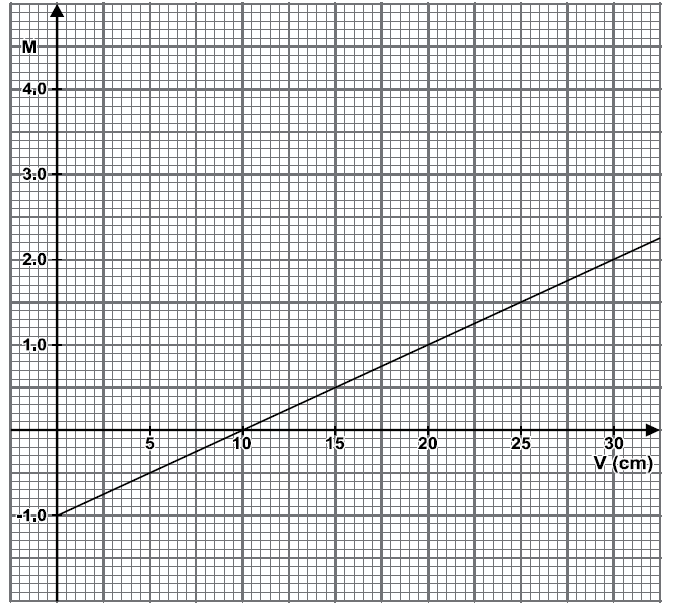
From the graph determine the focal length of the converging lens.
Date posted:
September 9, 2019
.
Answers (1)
-
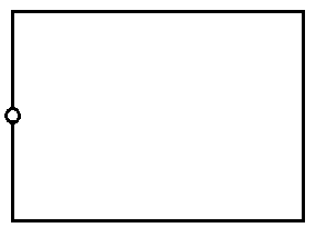
The figure below represents a pinhole camera.Sketch rays to show the formation of an enlarged image in the camera. Label both the image and the...
(Solved)
The figure below represents a pinhole camera.Sketch rays to show the formation of an enlarged image in the camera. Label both the image and the object.
Date posted:
September 9, 2019
.
Answers (1)
-
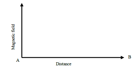
The figure below shows a bar magnet. Point A and B are in front of the magnet.On the axis provided, sketch a graph showing how...
(Solved)
The figure below shows a bar magnet. Point A and B are in front of the magnet.

On the axis provided, sketch a graph showing how the magnetic field strength changes from A to B.
Date posted:
September 9, 2019
.
Answers (1)
-
The following set-up was used by a student to determine the relative density of a cork
(Solved)
The following set-up was used by a student to determine the relative density of a cork

During the experiment, the following measurements were taken:-
- Weight of sinker in water = w1
- Weight of sinker in water and cork in air = w2
- Weight of sinker and cork in water = w3
(i) Write an expression for the up thrust on cork
(ii) Write an expression for the relative density of the cork
Date posted:
September 9, 2019
.
Answers (1)
-
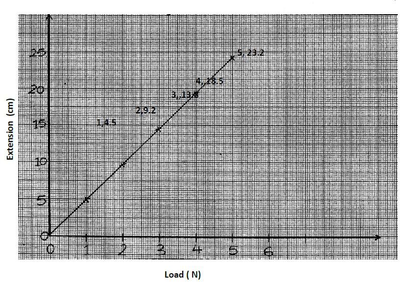
The graph shows how extension e of a helical spring varied with load, hanging on it. (cm).Determine from the graph, the proportionality constant of the...
(Solved)
The graph shows how extension e of a helical spring varied with load, hanging on it. (cm).Determine from the graph, the proportionality constant of the spring.
Date posted:
September 9, 2019
.
Answers (1)
-
A body of mass 4.0 kg held at a vertical height of 500cm is released to travel along a frictionless curved path as shown in...
(Solved)
A body of mass 4.0 kg held at a vertical height of 500cm is released to travel along a frictionless curved path as shown in the figure below.The 4.0kg mass strikes body of mass 6.0kg at rest immediately it reaches the horizontal. The bodies stick together and move in the same direction. Determine the velocity of the bodies immediately after collision.

Date posted:
September 9, 2019
.
Answers (1)
-
The figure below shows a simple pendulum of length 80 cm. the pendulum bob whose mass is 50 g oscillates between points A and B,...
(Solved)
The figure below shows a simple pendulum of length 80 cm. the pendulum bob whose mass is 50 g oscillates between points A and B, through its rest position C. A and B are both 10 cm higher than C.
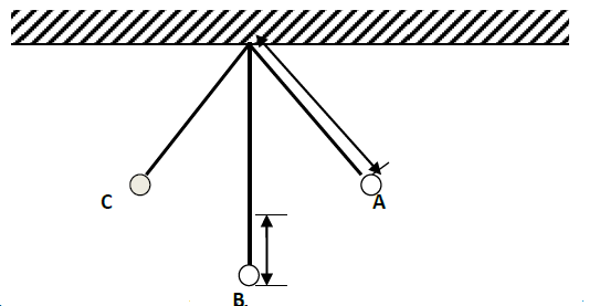
(a) State the form of energy possessed by the pendulum bob at point A
(b) Determine
(i) The velocity of the bob at point C
(ii) The tension in the string as the bob passes point C
(Take acceleration due to gravity g=10m/s2
Date posted:
September 9, 2019
.
Answers (1)
-
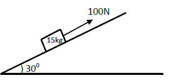
The figure below shows an inclined plane and a load of mass 15kg pulled by an effort of 100N.Find the efficiency of the machine.
(Solved)
The figure below shows an inclined plane and a load of mass 15kg pulled by an effort of 100N.Find the efficiency of the machine.
Date posted:
September 9, 2019
.
Answers (1)
-
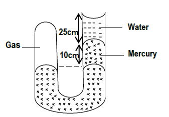
The figure below shows a U-tube manometer containing a gas, mercury and water. Calculate the gas pressure acting on the mercury. (Take atmospheric pressure to...
(Solved)
The figure below shows a U-tube manometer containing a gas, mercury and water. Calculate the gas pressure acting on the mercury. (Take atmospheric pressure to be 1.05 x 10⁵ pa, density of mercury and water to be 13600kg/m3 and 1000kg/m3 respectively).
Date posted:
September 9, 2019
.
Answers (1)
-
The figure below shows an electromagnetic relay being used to switch an electric motor on and off. The electromagnet consists of a coil of wire...
(Solved)
The figure below shows an electromagnetic relay being used to switch an electric motor on and off. The electromagnet consists of a coil of wire wrapped around a core. The motor in figure is switched off.
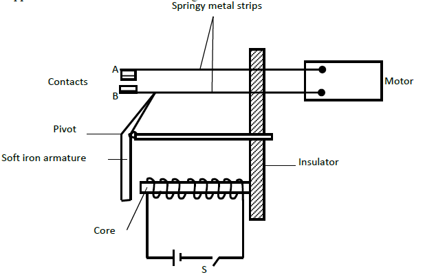
(a) Suggest suitable material for the core.
(b) What happens to the core when switch S is closed?
(c) Why do the contacts A and B close when the switch S is closed.
(d) When the switch S is opened, what will happen to;
(i) The core
(ii) Soft iron armature.
Date posted:
September 9, 2019
.
Answers (1)
-
The figure below shows a circuit with resistors and voltmeter connected to a battery.
(Solved)
The figure below shows a circuit with resistors and voltmeter connected to a battery.
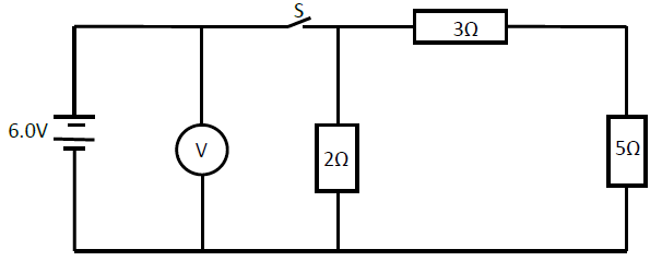
(i) If each cell has an internal resistance of 0.7 ohms, determine the total resistance in the circuit.
(ii) What amount of current flows through the 3 ohms resistor when the switch is closed?
(iii) What is the reading of the voltmeter when the switch S is
(I) Open
(II) Closed
(iv) Account for the difference between the answers in (I) and (II) above.
Date posted:
September 9, 2019
.
Answers (1)
-
A transformer has 200 turns in the primary coil and 1000 turns in the secondary coil. The primary coil is connected to an a.c source...
(Solved)
A transformer has 200 turns in the primary coil and 1000 turns in the secondary coil. The primary coil is connected to an a.c source producing 100 V and rated 500 W. The current delivered by the secondary circuit was found to be 0.95 A.
(i) Determine the efficiency of this transformer.
(ii) Explain why the efficiency is less than 100%.
Date posted:
September 6, 2019
.
Answers (1)
-
A bar magnet is pushed into a coil as shown in the figure below.
(Solved)
A bar magnet is pushed into a coil as shown in the figure below.
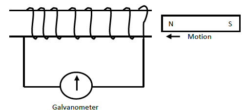
Explain what happens to the pointer of the galvanometer when the magnet is:
(i) Moved into the coil rapidly?
(ii) Remains stationary inside the coil?
Date posted:
September 6, 2019
.
Answers (1)
-
An electric kettle is rated at 1.8 kW, 240 V. Explain the choice of the safest fuse for the kettle. (the available fuses are 5...
(Solved)
An electric kettle is rated at 1.8 kW, 240 V. Explain the choice of the safest fuse for the kettle. (the available fuses are 5 A, 10A, and 20 A)
Date posted:
September 6, 2019
.
Answers (1)
-
A certain mass of hydrogen gas occupies a volume of 1.6m3 at a pressure of 1.5x10⁵Pa and a temperature of 120c. Determine the volume when...
(Solved)
A certain mass of hydrogen gas occupies a volume of 1.6m3 at a pressure of 1.5x10⁵Pa and a temperature of 120c. Determine the volume when the temperature is 00c at a pressure of 1.0x10³
Date posted:
September 6, 2019
.
Answers (1)
-
A cork of volume 100cm3 is floating on water. If the density of the cork is 0.25 gcm-3 and that of water is 1 gcm-3;
(a)...
(Solved)
A cork of volume 100cm3 is floating on water. If the density of the cork is 0.25 gcm-3 and that of water is 1 gcm-3;
(a) Calculate the mass of the cork
(b) Hence, find the upthrust force on the cork
(c) What minimum force is required to immerse the cork completely
(d) What is the effect on the upthrust force in a liquid when the temperature of the liquid is reduced?
Date posted:
September 6, 2019
.
Answers (1)
-
In an experiment to determine the specific latent heat of vaporization of water, steam at 100ºC was passed into water contained in a well-lagged copper...
(Solved)
In an experiment to determine the specific latent heat of vaporization of water, steam at 100ºC was passed into water contained in a well-lagged copper calorimeter. The following measurements were made:
- Mass of calorimeter = 60g
- mass of water + calorimeter = 145g
- Final mass of calorimeter + water + condensed steam = 156g
- Final temperature of the mixture = 48oC
[Specific heat capacity of water = 4200JKgˉ¹kˉ¹ and specific heat capacity of copper = 390JKgˉ¹kˉ¹
Determine the;
(i) mass of condensed steam.
(ii) The heat gained by the water and calorimeter if the initial temperature of the calorimeter and water is 20ºC.
(iii) Given that Lv is the specific latent heat of vaporization of steam, write an expression for the heat given out by steam.
(iv) Determine the value of Lv above
(v) State the assumption made in the above experiment
Date posted:
September 6, 2019
.
Answers (1)
-
The diagram below shows a graph of force against extension for a certain spring.
(Solved)
The diagram below shows a graph of force against extension for a certain spring.
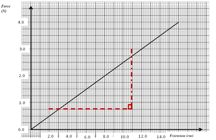
(i) What is the spring constant of the spring?
(ii) What force would cause two such springs placed side by side to stretch by 10cm
Date posted:
September 6, 2019
.
Answers (1)
-
The height of a mountain is 1360m. The barometer reading at the base of the mountain is 74cmHg. Given that the densities of mercury and...
(Solved)
The height of a mountain is 1360m. The barometer reading at the base of the mountain is 74cmHg. Given that the densities of mercury and air are 13,600Kgm-3 and 1.25Kgm-3 respectively, determine the barometer reading at the top of the mountain.
Date posted:
September 6, 2019
.
Answers (1)
-
The figure below is a simple hydraulic machine used to raise heavy loads.
(Solved)
The figure below is a simple hydraulic machine used to raise heavy loads.
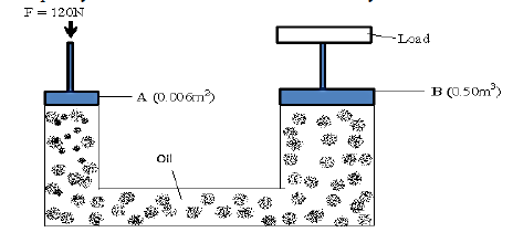
Calculate;
(i) The pressure exerted on the oil by the force applied at A
(ii) The load raised at B
(iii) Give two properties which make the oil suitable for use in this machine
Date posted:
September 6, 2019
.
Answers (1)